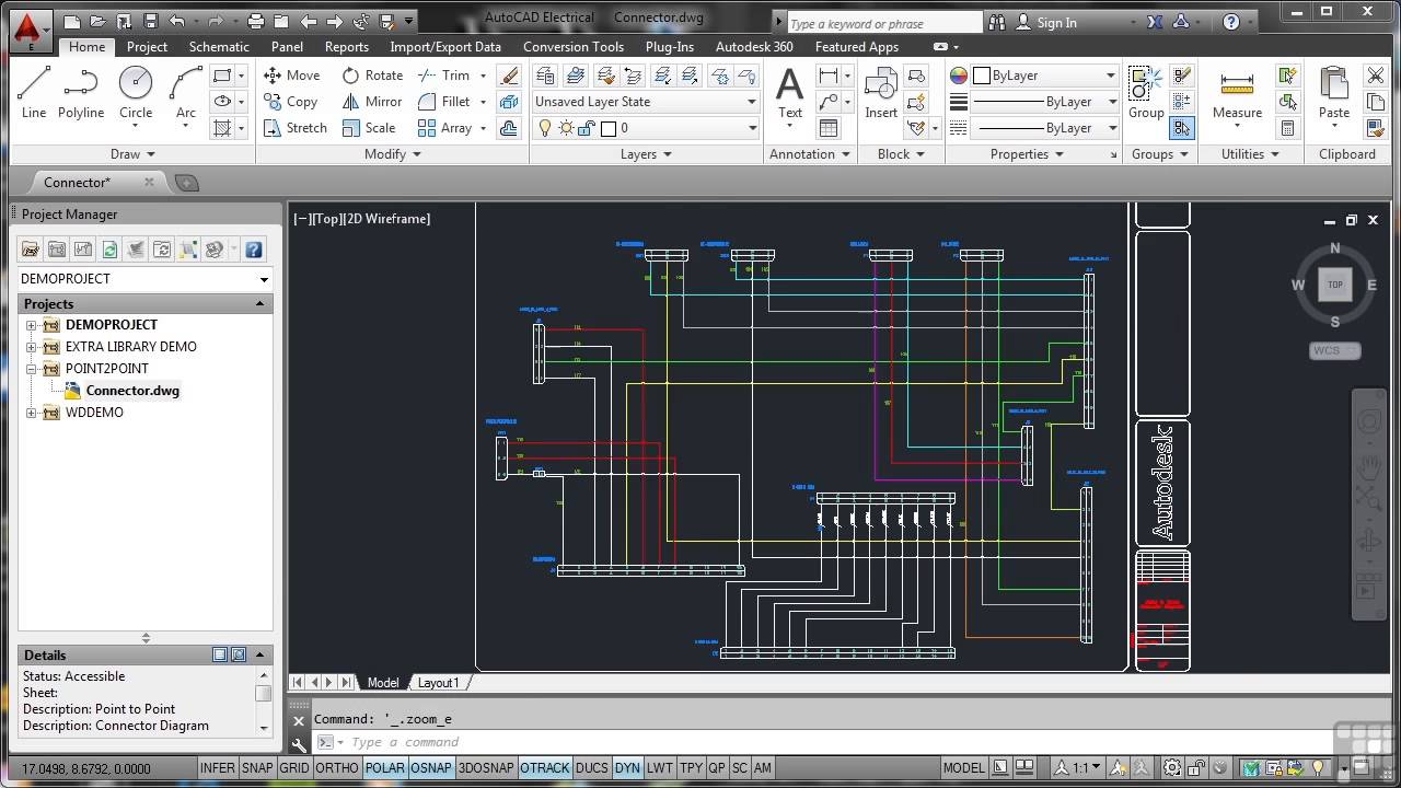
Exploring Efficiency and Precision: A Comprehensive Guide to Using the Connector Drawing Tool in Autodesk Electrical

Autodesk Electrical equips designers with an array of specialized tools to streamline the creation of intricate electrical schematics and designs, and among them, the Connector Drawing tool shines for its ability to enhance efficiency and precision in designing electrical connectors. This extensive guide aims to provide users with a comprehensive understanding of how to effectively utilize this tool, offering step-by-step instructions, best practices, and expert insights to help users master the art of connector drawing in Autodesk Electrical.
Understanding the Connector Drawing Tool
The Connector Drawing tool in Autodesk Electrical is specifically designed to facilitate the creation of detailed and accurate representations of electrical connectors within schematic diagrams. By leveraging this tool, users can efficiently design connectors with multiple pins or terminals, customize connector properties, and ensure seamless integration with other components in their electrical designs. Key features of the Connector Drawing tool include:
- Versatility: Supports the creation of various types of connectors, including terminal blocks, multi-pin connectors, and cable connectors.
- Customization: Allows users to customize connector properties, such as pin assignments, pin numbering, and connector labels, to meet specific project requirements.
- Integration: Seamlessly integrates connectors into schematic diagrams, enabling users to establish connections between components and visualize electrical pathways.
Step-by-Step Guide to Using the Connector Drawing Tool
Step 1: Accessing the Connector Drawing Tool
- Launch Autodesk Electrical and open the schematic drawing where you wish to add a connector.
- Navigate to the “Schematic” tab on the ribbon toolbar.
- Click on the “Connector Drawing” tool icon to activate the Connector Drawing mode.
Step 2: Creating a Connector
- With the Connector Drawing mode activated, click on the location within the schematic where you want to place the connector.
- Specify the type of connector you wish to create, such as a terminal block or multi-pin connector, from the Connector Drawing palette.
- Click to place the connector in the desired location within the schematic.
Step 3: Customizing Connector Properties
- After placing the connector, use the Connector Properties dialog box to customize connector properties, such as pin assignments, pin numbering, and connector labels.
- Specify the number of pins or terminals, pin spacing, and orientation of the connector as needed.
Step 4: Adding Pins or Terminals
- With the connector selected, use the “Add Pins” or “Add Terminals” command to add individual pins or terminals to the connector.
- Specify the properties of each pin or terminal, such as pin number, pin type, and pin function.
Step 5: Connecting Components
- Once the connector is created and customized, establish connections between the connector and other components in the schematic.
- Use the “Wire” tool to draw connection lines between the connector pins or terminals and corresponding components, such as relays, switches, or sensors.
Best Practices for Using the Connector Drawing Tool
To optimize your use of the Connector Drawing tool in Autodesk Electrical, consider the following best practices:
- Consistency: Maintain consistency in connector properties, such as pin assignments and pin numbering, to ensure clarity and readability in schematics.
- Documentation: Document connector specifications, pin assignments, and wiring diagrams for reference and future use.
- Collaboration: Foster collaboration and communication among design team members to ensure alignment and coordination in connector design and usage.
- Validation: Verify connector functionality and connectivity by performing thorough testing and validation of electrical circuits.
Conclusion
The Connector Drawing tool in Autodesk Electrical is a valuable asset for designers seeking to enhance efficiency, precision, and clarity in their schematic diagrams. By following the step-by-step guide and best practices outlined in this comprehensive guide, users can effectively harness the power of this tool to create detailed and accurate representations of electrical connectors, streamline the design process, and achieve superior results in their projects. Whether you’re a seasoned professional or a novice user, mastering the Connector Drawing tool will empower you to elevate your electrical design capabilities and optimize your workflow with confidence.


