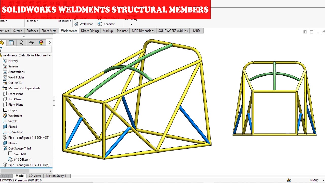
Unlocking the Power of Structural Member Creation in Weldments Using SolidWorks: A Comprehensive Guide

SolidWorks, a leading 3D CAD software, offers robust tools for creating structural members in weldments. Whether you’re designing industrial machinery, architectural structures, or intricate frameworks, understanding how to utilize SolidWorks’ structural member creation capabilities can significantly enhance your design process. In this comprehensive guide, we’ll delve into the step-by-step process of creating structural members in a weldment using SolidWorks, covering everything from selecting profiles to customizing dimensions and properties.
1. Understanding Weldments and Structural Members:
- Weldments in SolidWorks allow you to create welded structures by assembling individual structural members.
- Structural members can include beams, tubes, angles, channels, and custom profiles, which form the building blocks of weldment assemblies.
- SolidWorks provides dedicated tools for creating, modifying, and assembling structural members, making it an ideal platform for structural design and fabrication.
2. Accessing the Structural Member Tool:
- To create structural members in a weldment, first, open a new or existing SolidWorks part document.
- Navigate to the Weldments tab in the Command Manager, where you’ll find the Structural Member tool.
- Click on the Structural Member tool to access the profile selection menu and begin creating your structural members.
3. Selecting Profile Types:
- SolidWorks offers a library of standard structural profiles, including beams, tubes, angles, channels, and more.
- Click on the Profile Type dropdown menu to browse through the available profile categories.
- Select the desired profile type from the list, such as ANSI Inch, ISO, DIN, or custom profiles.
4. Choosing Profile Sizes:
- Once you’ve selected the profile type, SolidWorks will display a list of available profile sizes within that category.
- Click on the Size dropdown menu to view the available sizes for the selected profile type.
- Choose the appropriate size for your structural member based on your design requirements and specifications.
5. Sketching the Path:
- After selecting the profile type and size, SolidWorks prompts you to sketch the path along which the structural member will be created.
- Use the Sketch tools to draw a line, arc, or other sketch geometry that represents the path of the structural member.
- Ensure that the sketch is fully defined and closed to create a continuous structural member.
6. Configuring Member Parameters:
- With the sketch path defined, SolidWorks will generate the structural member along the specified path.
- You can configure various parameters for the structural member, including length, orientation, placement, and alignment.
- SolidWorks provides options for controlling the position and orientation of the structural member relative to the sketch path, allowing you to create complex geometries with ease.
7. Customizing Dimensions and Properties:
- SolidWorks offers extensive customization options for adjusting the dimensions and properties of structural members.
- Use the Dimension tool to add dimensions to the structural member, allowing you to precisely control its size and proportions.
- You can also modify material properties, such as material type, density, and color, to match your design specifications.
8. Adding Additional Members:
- Once the first structural member is created, you can continue adding additional members to the weldment assembly.
- Repeat the process of selecting profile types, sizes, sketching paths, and configuring parameters for each structural member as needed.
- SolidWorks provides intuitive tools for aligning, mirroring, and copying structural members to streamline the assembly process.
9. Modifying and Editing Members:
- SolidWorks offers robust editing tools for modifying and adjusting structural members to fit your design requirements.
- You can easily resize, move, rotate, and mirror members using the Edit Feature and Move/Copy tools.
- Additionally, SolidWorks provides options for trimming, extending, and mitering members to create precise connections and joints.
10. Validating and Analyzing Members:
- Before finalizing your weldment design, it’s essential to validate and analyze structural members to ensure structural integrity and performance.
- SolidWorks offers simulation tools, such as SolidWorks Simulation, for performing structural analysis and stress testing on weldments.
- You can also use the Interference Detection feature to identify and resolve any clashes or interference between components within the weldment assembly.
Conclusion:
- Creating structural members in weldments using SolidWorks is a straightforward process that requires careful attention to detail and adherence to best practices.
- By following the steps outlined in this guide and leveraging SolidWorks’ powerful tools and features, you can create precise and accurate structural members that meet the requirements of your project.
- Whether you’re designing industrial machinery, architectural structures, or intricate frameworks, SolidWorks provides the capabilities you need to streamline your design process and achieve exceptional results in weldment fabrication and assembly.


