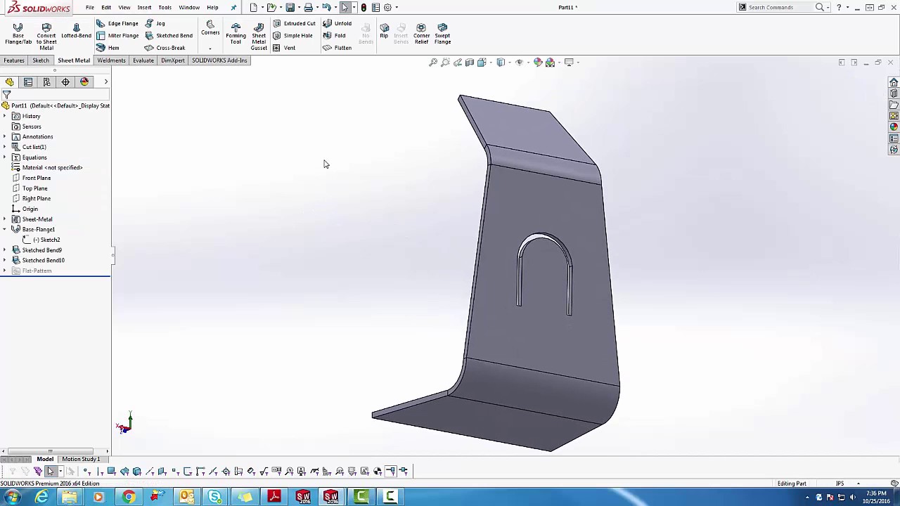
Mastering Sheet Metal Design: A Comprehensive Guide to Adding Bends in SolidWorks

Adding bends to sheet metal parts in SolidWorks is a fundamental skill for engineers and designers working in industries such as manufacturing, aerospace, automotive, and more. SolidWorks provides powerful tools and features to create precise and accurate sheet metal designs, including the ability to add bends to sheet metal parts with ease. In this comprehensive guide, we will explore the step-by-step process of adding bends to sheet metal parts in SolidWorks, covering everything from creating a basic sheet metal part to applying bends and configuring bend parameters.
1. Creating a Sheet Metal Part:
- Open SolidWorks and create a new part document.
- Switch to the Sheet Metal tab in the Command Manager.
- Click on the Base Flange/Tab feature or use the Insert > Sheet Metal > Base Flange/Tab command.
- Define the parameters for the base flange, including material thickness, bend radius, and dimensions.
2. Sketching Bends:
- Once the base flange is created, switch to the Sketch tab in the Command Manager.
- Sketch the profiles for the bends you want to add to the sheet metal part. Ensure that the sketches are closed and fully defined.
- Use lines, arcs, and other sketch tools to create the desired bend geometry. You can also use existing edges of the sheet metal part as references for sketching bends.
3. Adding Bends:
- Return to the Sheet Metal tab in the Command Manager.
- Click on the Edge Flange feature or use the Insert > Sheet Metal > Edge Flange command.
- Select the sketch profiles that define the bends you want to add.
- Define the parameters for the edge flange, including bend angle, bend radius, and direction.
- Preview the bend geometry and make any necessary adjustments.
4. Configuring Bend Parameters:
- SolidWorks provides various options for configuring bend parameters to achieve the desired results.
- You can adjust the bend radius, bend angle, relief type, and other parameters in the Edge Flange PropertyManager.
- Experiment with different values to see how they affect the bend geometry and overall design of the sheet metal part.
- SolidWorks also offers advanced bend options, such as hemming, closed corner, and tear relief, which can be accessed through the Edge Flange PropertyManager.
5. Modifying Bends:
- Once bends are added to the sheet metal part, you can easily modify them using SolidWorks’ editing tools.
- To change the bend radius or angle, simply edit the corresponding parameters in the Edge Flange PropertyManager.
- You can also delete, suppress, or unsuppress bends as needed to refine the design.
- SolidWorks provides robust editing capabilities for sheet metal parts, allowing you to make quick and precise modifications to bends and other features.
6. Flattening and Unfolding:
- After adding bends to the sheet metal part, you may need to flatten or unfold it to create a flat pattern for manufacturing.
- SolidWorks offers a Flatten feature that automatically unfolds the sheet metal part, allowing you to visualize the flat pattern.
- You can also manually unfold bends using the Unfold feature, which gives you greater control over the unfolding process.
- Ensure that the flat pattern is accurate and free of errors before proceeding to manufacturing.
7. Verifying Design Intent:
- Throughout the process of adding bends to the sheet metal part, it’s essential to verify the design intent and ensure that the final product meets the required specifications.
- Use SolidWorks’ visualization tools, such as Section View and Measure, to inspect the geometry of bends and other features.
- Perform simulation analyses, such as Finite Element Analysis (FEA), to validate the structural integrity and manufacturability of the sheet metal part.
- Collaborate with colleagues and stakeholders to review the design and address any concerns or suggestions for improvement.
8. Documentation and Manufacturing:
- Once the design is finalized and verified, generate detailed drawings and documentation for manufacturing.
- SolidWorks provides tools for creating dimensioned drawings, bill of materials (BOM), and other documentation required for production.
- Communicate with manufacturers and fabricators to ensure that the design specifications are clearly understood and followed during the manufacturing process.
- Monitor the manufacturing process to ensure that the sheet metal part is fabricated accurately and according to the approved design.
Conclusion:
- Adding bends to sheet metal parts in SolidWorks is a straightforward process that requires careful attention to detail and adherence to best practices.
- By following the steps outlined in this guide and leveraging SolidWorks’ powerful tools and features, you can create precise and accurate sheet metal designs that meet the requirements of your project.
- Whether you’re designing complex aerospace components or simple enclosures for electronic devices, SolidWorks provides the capabilities you need to create high-quality sheet metal parts efficiently and effectively.


