
Comprehensive Guide: How to Bake a Cake
Baking a cake is not just a culinary task; it's an art form that brings joy and satisfaction to both...
Baking a cake is not just a culinary task; it's an art form that brings joy and satisfaction to both...

Dealing with a clogged drain is a common household nuisance that can disrupt daily routines and lead to frustration. Whether...
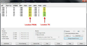
In the realm of electrical design, ensuring connectivity and clarity are paramount. Autodesk Electrical's Wire From/To List tool emerges as...
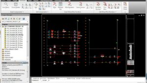
Autodesk Electrical offers a comprehensive Component Library feature that serves as a centralized repository for storing, managing, and accessing a...

Autodesk Electrical offers a wealth of tools and features to streamline the design process, and among them, the Electrical Content...

Autodesk Electrical offers a plethora of features to streamline the design process, and among them, the ability to create and...
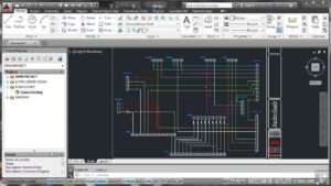
Autodesk Electrical equips designers with an array of specialized tools to streamline the creation of intricate electrical schematics and designs,...