


How to Host a Website on a Local Server Using XAMPP
How to Host a Website on a Local Server Using XAMPP For web developers who wish to test, build, or...
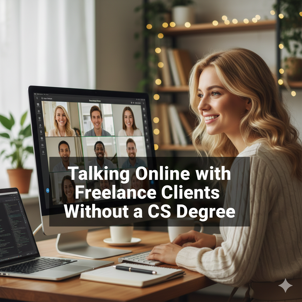
 How to Use “Claude Code” to Build Custom Software Tools for Your Freelance Clients Without a CS Degree
  The Best Ergonomic Home Office Setup for Freelancers: Reducing Neck Pain and Eye Strain for Long Sessions
  How to Find International Clients Who Pay in Stablecoins: A Freelancer’s Guide to Crypto Payments
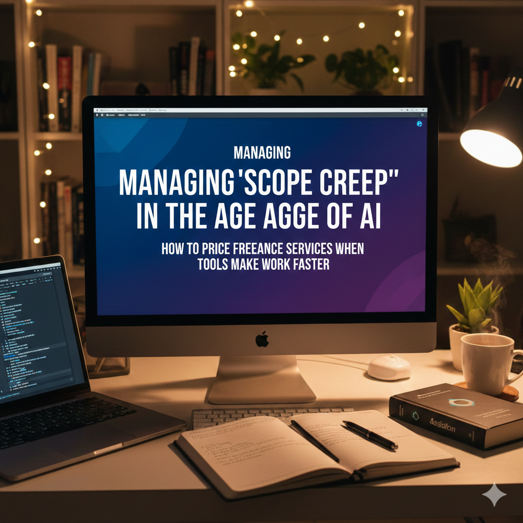
  Managing “Scope Creep” in the Age of AI: How to Price Freelance Services When Tools Make Work Faster
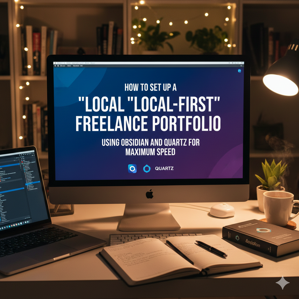
  How to Set Up a “Local-First” Freelance Portfolio Using Obsidian and Quartz for Maximum Speed
 How to Host a Website on a Local Server Using XAMPP For web developers who wish to test, build, or...

How to Protect Your Data from Viruses and Cyber Threats In the modern digital world, it is very necessary to...

How to Fix Common Computer Startup Problems Like a Technician When your computer is unable to start up correctly, it...
How to Install and Configure Windows 11 from a USB Drive Installing Windows 11 via a USB drive is one...

Step-by-Step Guide How to Partition and Format a Hard Drive Safely Organizing storage, getting new drives ready for usage, and...

The Evolution of Computer Hardware: From Vacuum Tubes to Quantum Chips Throughout the history of computer hardware, human ingenuity, perseverance,...

What Role Does Artificial Intelligence Play in the Field of Personal Computing? The term "artificial intelligence" (AI) is no longer...