


What are the Top Freelance Skills That Will Be in Demand in 2025? Here’s How to Learn Them!
What are the Top Freelance Skills That Will Be in Demand in 2025? Here's How to Learn Them! The world...
 How to Set Up a “Private Cloud” at Home Using TrueNAS: Bypassing Subscription Fees for Good
  The Guide to “Green IT”: How to Reduce Your Company’s Server Energy Consumption and Carbon Footprint
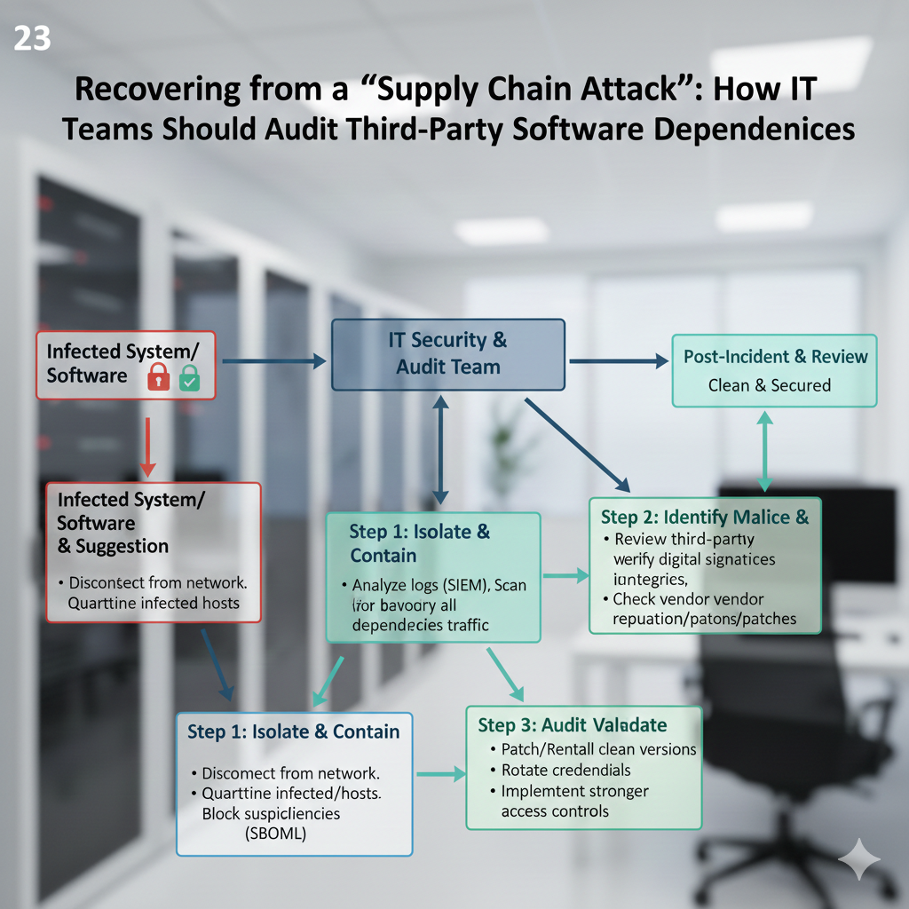
  Recovering from a “Supply Chain Attack”: How IT Teams Should Audit Third-Party Software Dependencies
  How to Use “Multi-Agent Systems” to Automate Customer Service Ticketing in a Small IT Department
  The Best IT Practices for Managing a “Bring Your Own Device” (BYOD) Policy in 2026
 What are the Top Freelance Skills That Will Be in Demand in 2025? Here's How to Learn Them! The world...

In what ways is innovation helping to close the education gap? The ability to get a high-quality education continues to...

Huawei's flagship phones the Pura 80 Series violate all the rules in the Smartphone Industry. The Pura 80 series, which...

Smartphones Set to Be Released in June — During this month what is new? The month of June 2025 has...

Using these phones WhatsApp will no longer function properly. Beginning on June 1, 2025, Meta will begin to phase off...

With the introduction of Gemini, Google is attempting to steer clear of the errors of the past Google Glasses Prepare...

WhatsApp Web Will Unite All Chat Media Soon. The online version of WhatsApp is now in the process of building...