Comprehensive Guide: How to Brew Tea Leaves for Perfect Flavor
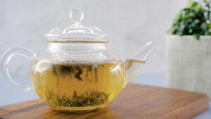
Brewing tea leaves is a time-honored tradition that involves more than just steeping—it's about unlocking the nuanced flavors and aromas...
Brewing tea leaves is a time-honored tradition that involves more than just steeping—it's about unlocking the nuanced flavors and aromas...

Cleaning a cutting board is essential not only for maintaining hygiene but also for preserving its quality and extending its...

Polishing men's shoes is not just about enhancing their appearance; it's a ritual that extends the life of your footwear...

Making a bed is more than just arranging sheets and pillows—it's a daily ritual that sets the tone for comfort...

A squeaky door can be a persistent annoyance in any home or building, disrupting peace and privacy with its repetitive...

Optimizing startup programs is crucial for improving your computer's boot time and overall performance. When too many programs launch automatically...

Setting up dual monitors can significantly enhance productivity and multitasking capabilities by expanding your desktop workspace. Whether for work, gaming,...