Mastering Deep Learning with TensorFlow: A Comprehensive Guide
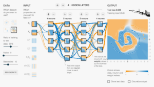
Introduction to TensorFlow TensorFlow is an open-source platform for machine learning and artificial intelligence developed by Google. It provides a...
Introduction to TensorFlow TensorFlow is an open-source platform for machine learning and artificial intelligence developed by Google. It provides a...
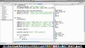
Introduction to SQLite SQLite is a lightweight, file-based database engine that doesn't require a separate server process. It's embedded into...
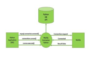
Introduction Python, with its simplicity and versatility, has become a popular choice for interacting with databases. This article will delve...
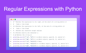
Introduction to Regular Expressions Regular expressions, often abbreviated as regex or regexp, are sequences of characters that define a search...

Managing remote teams has become increasingly prevalent in today's globalized and digital workforce. Effective management of remote teams requires unique...

Negotiating contracts is a critical skill for businesses and professionals involved in various transactions, agreements, and partnerships. Effective contract negotiation...

Choosing the right business software is crucial for enhancing productivity, streamlining operations, and achieving strategic objectives within an organization. Whether...