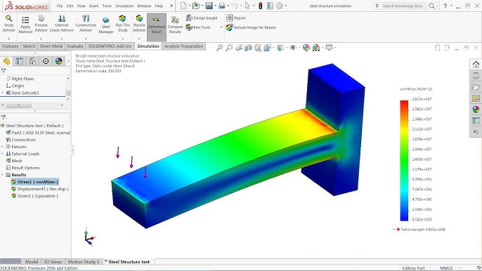
Mastering Stress Analysis in SolidWorks: A Comprehensive Guide to Evaluating Structural Integrity and Performance

Performing stress analysis on a part in SolidWorks is a crucial step in the design process, enabling engineers and designers to assess the structural integrity and performance of their designs under various loading conditions. SolidWorks provides powerful simulation tools that allow users to analyze stress, deformation, and factor of safety, helping to identify potential design flaws and optimize designs for real-world applications. In this comprehensive guide, we will explore the step-by-step process of performing stress analysis on a part in SolidWorks, covering everything from setting up a simulation study to interpreting results and optimizing designs.
1. Understanding Stress Analysis in SolidWorks:
- Stress analysis in SolidWorks involves simulating the behavior of a part or assembly under applied loads and boundary conditions.
- By analyzing stress distribution, deformation, and factor of safety, engineers can evaluate the structural performance of their designs and make informed decisions to improve reliability and efficiency.
2. Setting Up a Simulation Study:
- To perform stress analysis, open the desired part or assembly in SolidWorks.
- Navigate to the Simulation tab in the Command Manager and click on the New Study icon to create a new simulation study.
- Choose the type of analysis you want to perform, such as static, thermal, or nonlinear analysis, and specify the study properties and settings.
3. Applying Loads and Boundary Conditions:
- Once the simulation study is set up, apply loads and boundary conditions to simulate real-world operating conditions.
- Use the External Loads and Fixtures tools to apply forces, pressures, torques, and displacements to the part.
- Specify the magnitude, direction, and location of loads and constraints based on the application requirements.
4. Meshing the Part:
- Before running the analysis, mesh the part to discretize the geometry into smaller elements for accurate simulation results.
- SolidWorks provides automatic and manual meshing tools to generate high-quality meshes that capture the geometric details and features of the part.
- Adjust the mesh size and settings to ensure adequate resolution and convergence of the solution.
5. Running the Analysis:
- With loads, boundary conditions, and meshing applied, run the stress analysis by clicking on the Run icon in the Simulation tab.
- SolidWorks solves the finite element model to calculate stress, deformation, and other mechanical properties of the part.
- Monitor the progress of the analysis and review any warning messages or errors that may arise during the solution process.
6. Interpreting Results:
- Once the analysis is complete, review and interpret the results to gain insights into the structural behavior of the part.
- SolidWorks provides visualization tools, such as contour plots, displacement plots, and stress plots, to visualize and analyze the results.
- Evaluate stress distribution, deformation, factor of safety, and other mechanical properties to assess the performance of the design.
7. Optimizing the Design:
- Based on the results of the stress analysis, make design modifications to improve the structural performance and reliability of the part.
- Iterate on the design by adjusting geometry, material properties, or loading conditions to reduce stress concentrations and increase factor of safety.
- Use SolidWorks’ parametric modeling and simulation-driven design tools to explore design alternatives and optimize the design for maximum efficiency.
8. Validating Results and Verification:
- After optimizing the design, validate the results of the stress analysis through physical testing or verification against empirical data.
- Compare simulation results with experimental measurements to ensure accuracy and reliability of the simulation model.
- Iterate on the design as necessary based on validation results and refine the simulation model for future analysis.
9. Documenting and Reporting:
- Document the stress analysis process, results, and findings in a comprehensive report for internal or external stakeholders.
- Include details such as simulation setup, boundary conditions, meshing parameters, analysis results, and design recommendations.
- Use visualizations, tables, and charts to communicate complex information effectively and support decision-making.
10. Conclusion:
- Performing stress analysis on a part in SolidWorks is a critical aspect of the design process, enabling engineers and designers to assess the structural integrity and performance of their designs.
- By following the steps outlined in this guide and leveraging SolidWorks’ powerful simulation tools, users can gain valuable insights into the behavior of their designs and make informed decisions to optimize performance and reliability.
- Whether designing mechanical components, structural assemblies, or complex systems, SolidWorks empowers users to simulate and analyze designs with confidence, ensuring they meet the highest standards of quality and safety.


